(copy 7)
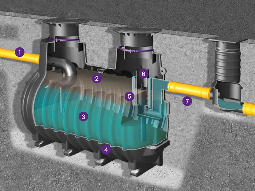
1. Inlet
Wastewater from one or more discharge points is fed into the separator via the inlet.
2. Oil storage tank
Separated light liquids are retained in the oil reservoir and stored there until disposal.
3. Separation chamber
The separation process, whereby light liquids and sludge are separated from the wastewater stream, takes place in the separation chamber.
4. Sludge trap
Sediments and other settleable solids are retained and stored in the sludge trap.
5. Coalescence filter
The coalescence filter increases the separation efficiency of the separator.
6. Overflow barrier
The overflow barrier prevents the oil separator from overflowing and contaminated wastewater from entering the sewer system.
7. Outlet
The treated wastewater is discharged via the outlet to a sampling point and then into the sewer.
What happens inside a light liquid separator?
Light liquid separators operate on the principle of gravity: due to the difference in density between water, oil, petrol and dirt particles (sludge), the various substances separate naturally within the separation tank. If required, the separation efficiency can be further improved by using a coalescing filter insert.
(copy 8)
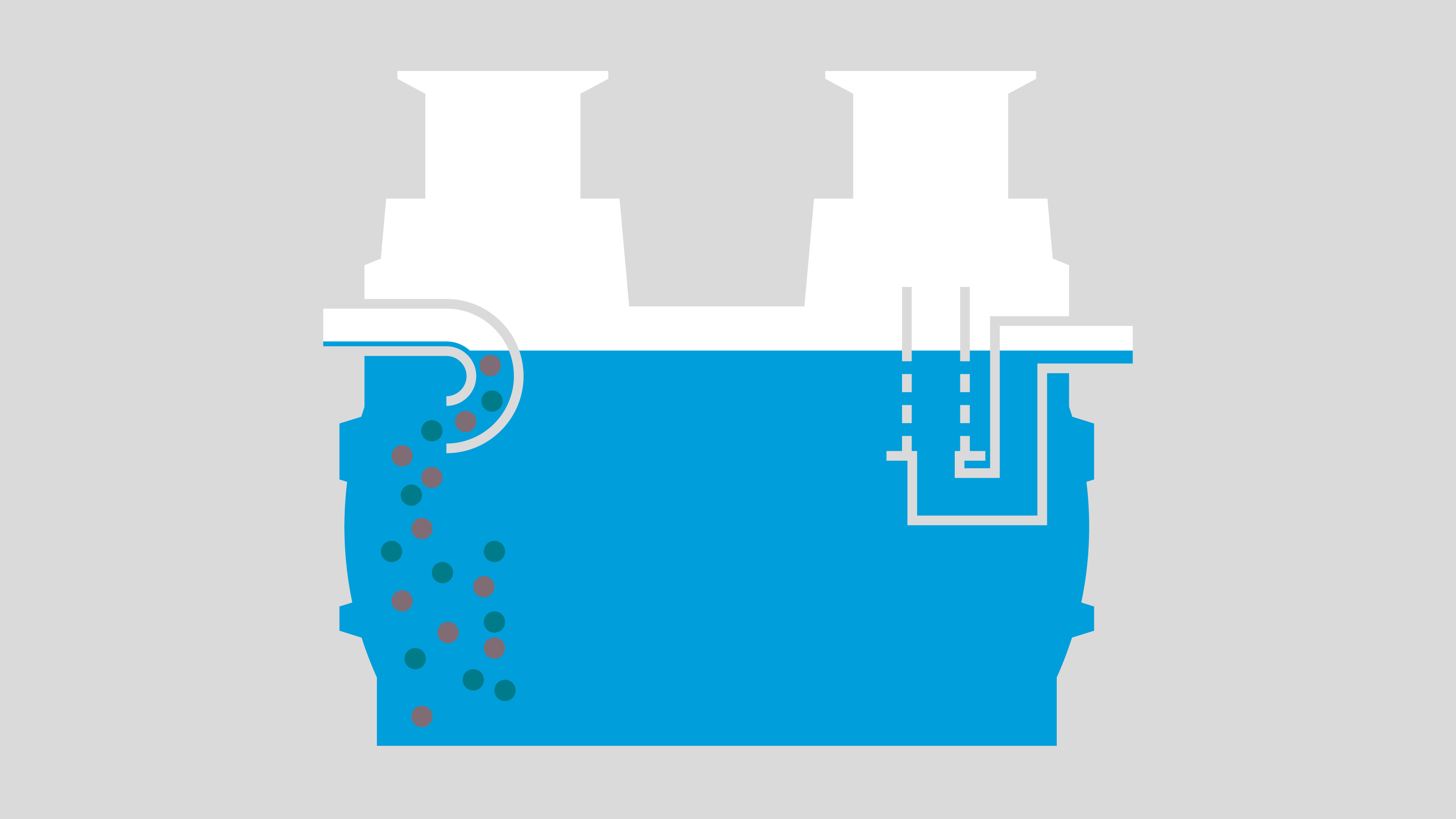
Wastewater discharge
The contaminated wastewater is fed into the light liquid separator, where the flow is largely stabilised due to the large volume of the tank.
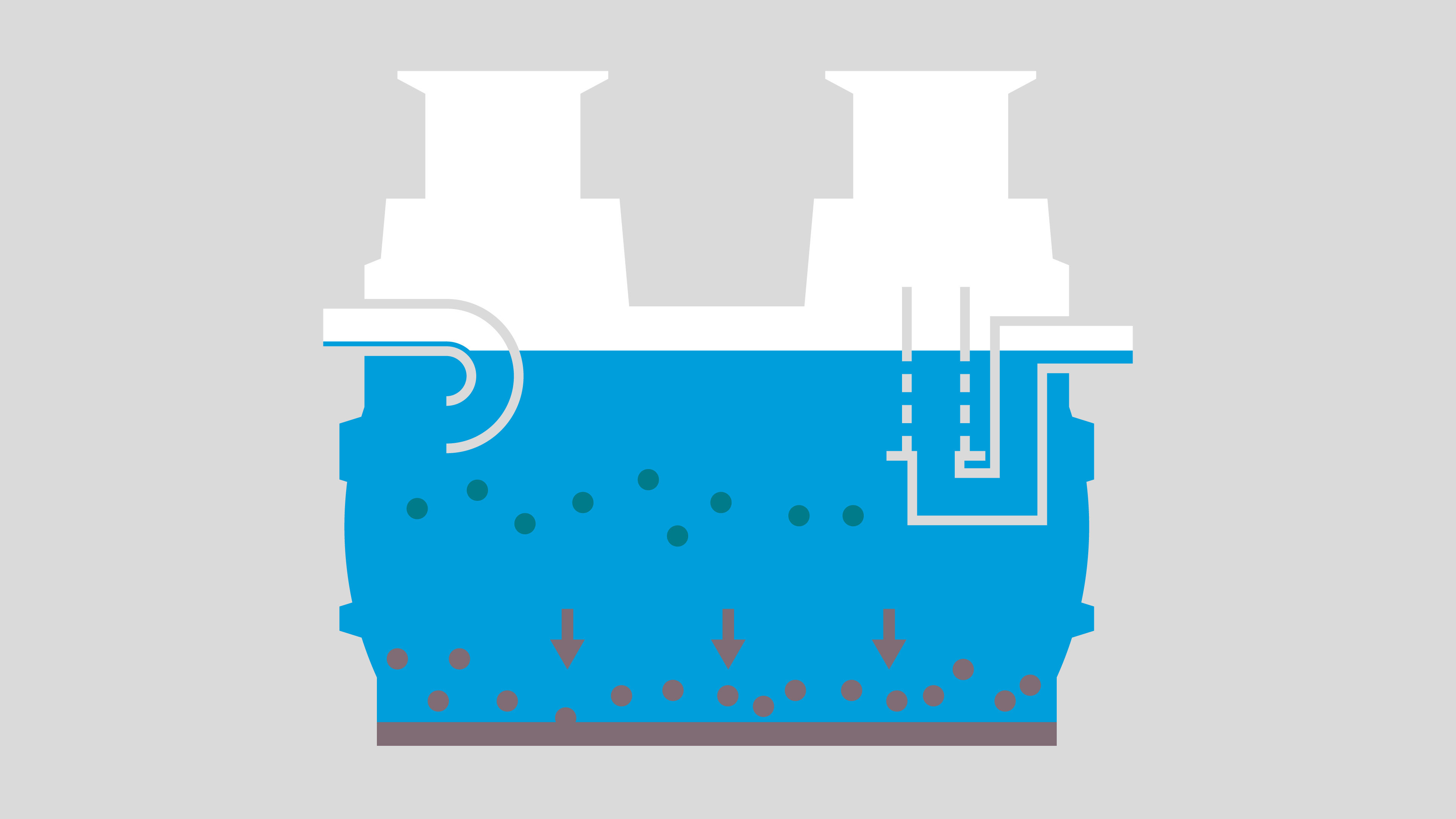
sludge build-up
In the flow-calming tank, materials that are heavier than water sink to the bottom and settle in the sludge trap.
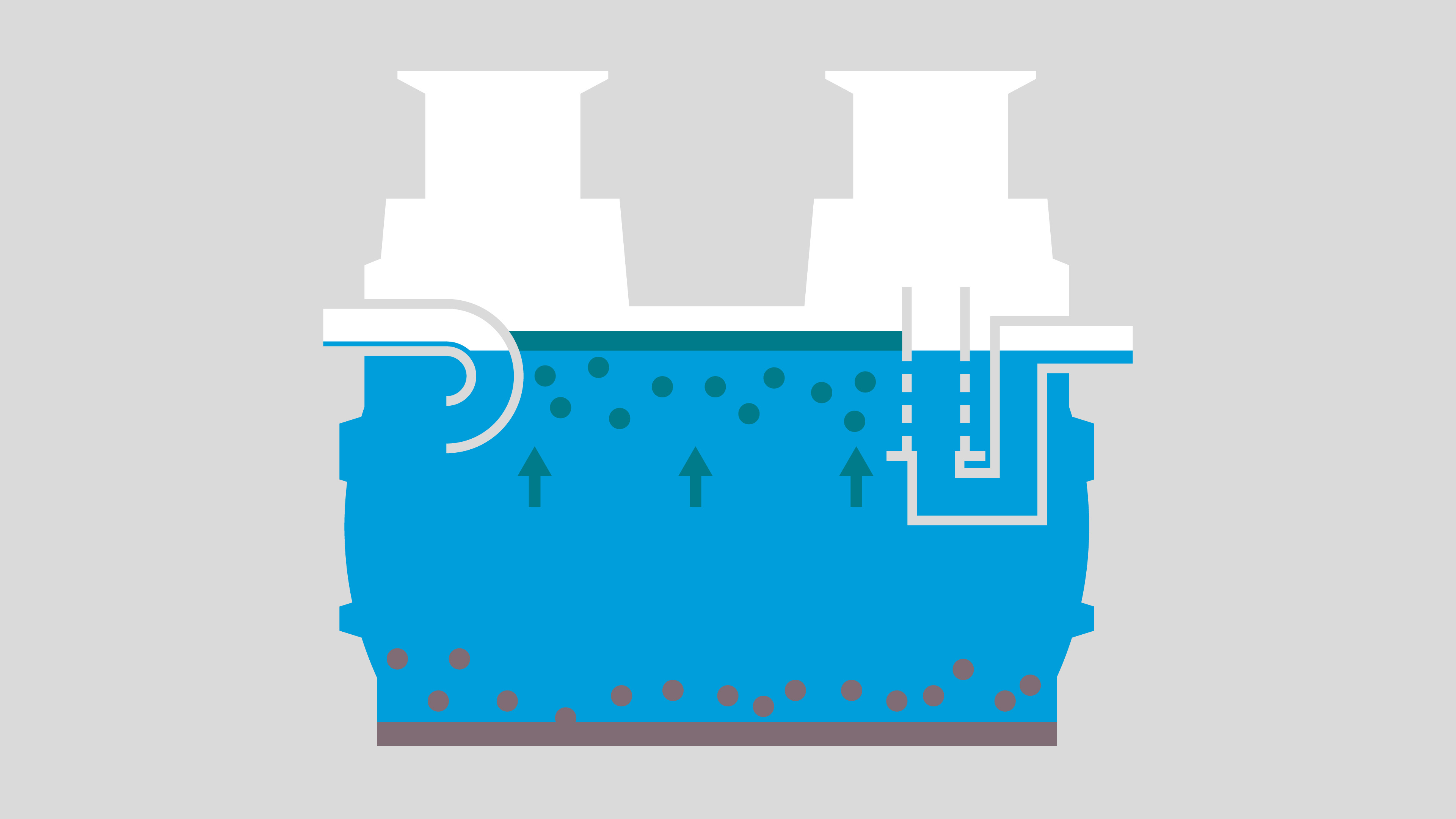
Formation of a light liquid layer
Oil and petrol rise to the top, where they form a layer of light liquid that is retained in the separator.
What are light liquid separators used for?
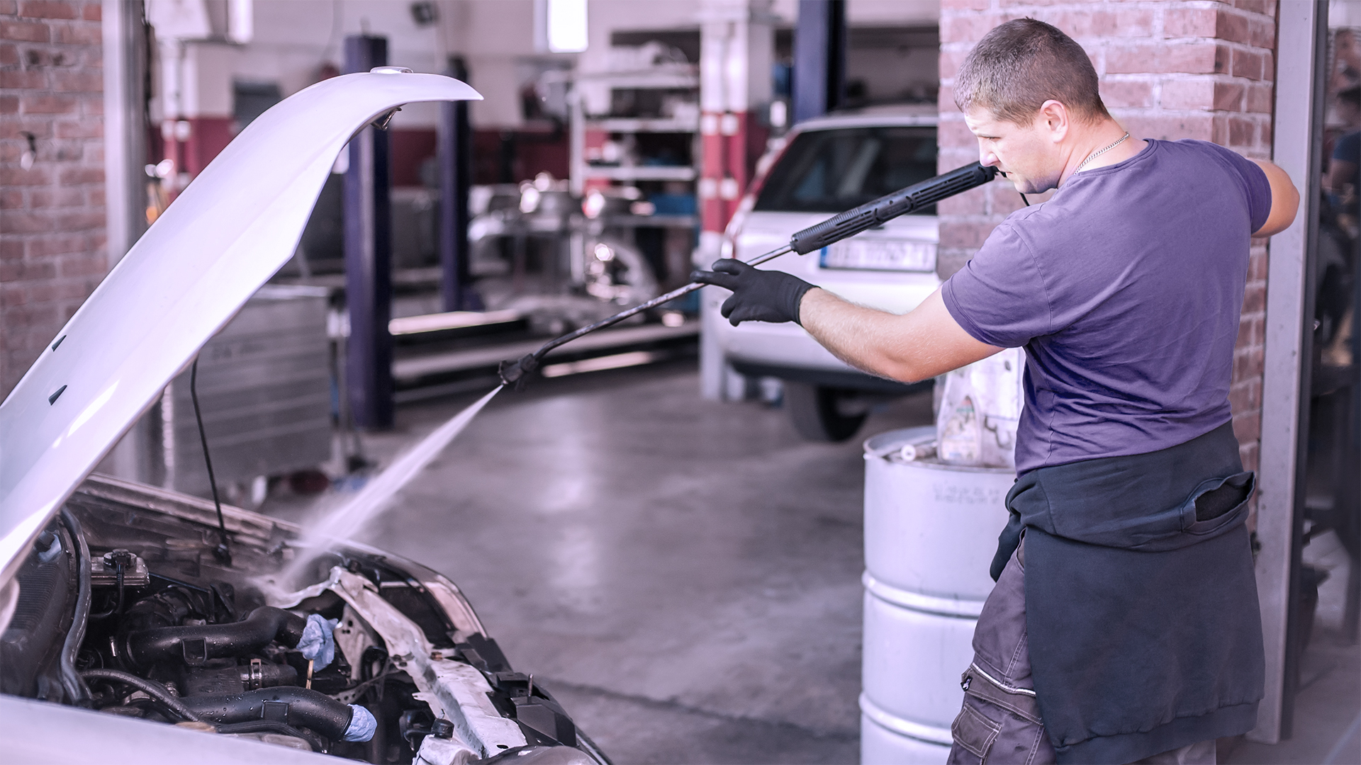
Light liquid separators are used wherever wastewater is at risk of being contaminated by fuels and/or lubricants. This applies, for example, to the automotive sector, such as petrol stations, car washes and garages, as well as car parks, scrap yards and refuelling stations. In such establishments, it is absolutely essential to pre-treat the wastewater – not least because even a single drop of petrol is enough to render a cubic metre of water unusable.
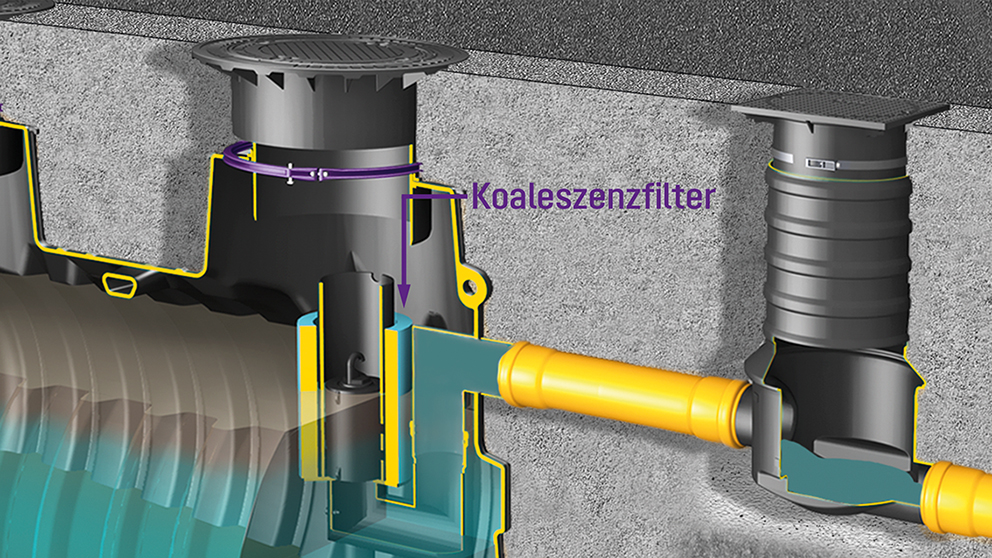
coalescence separator
What is the difference between light liquid separators in System A (class I) and System B (class II)?
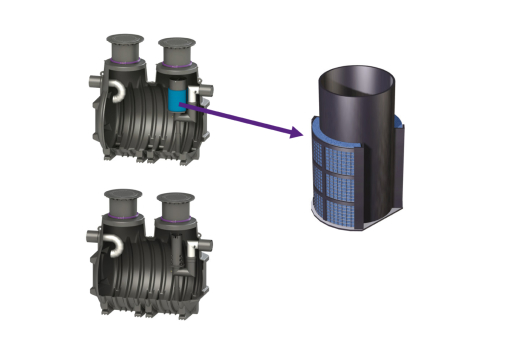
“System B” (class II) light liquid separators operate exclusively on the principle of gravity. These separators are also referred to as oil/fuel separators. A “System A” (class I) light liquid separator additionally incorporates a coalescing filter insert. The coalescence filter insert increases the separator’s performance by capturing even the smallest light liquid droplets and feeding them into the oil reservoir. Such a filter insert can also be used to retrofit a “System A” (class I) separator into a “System B” (class II) separator.
Separators “System B” (class II) may achieve a maximum permissible hydrocarbon content of 100 mg/l when tested in accordance with DIN EN 858-1, Section 8.3.3. For ‘System A’ (Class I) separators, this value is 5 mg/l. It can be deduced from these differing requirements that the ‘System A’ (Class I) separator achieves a significantly higher separation efficiency than the ‘System B’ (Class II) separator.
What is coalescence?
In physics, coalescence refers to the merging of separate substances into a single mass. Coalescence can be observed, for example, when several droplets of the same liquid come into contact with one another and merge to form a larger droplet. Separator systems fitted with coalescence filters utilise this principle to separate out the smallest particles of light liquid.
How does a coalescing filter cartridge work?
In a light liquid separator fitted with a coalescing filter cartridge, the wastewater to be treated flows against an oleophilic (‘oil-attracting’) material, such as an open-cell polyurethane foam. Light liquid particles contained in the wastewater adhere to this material and gradually coalesce with one another. As the oil droplets have greater buoyancy than smaller particles, they eventually rise to the top and are absorbed by the oil layer.
(copy 9)

1. Formation of an oil film
Non-buoyant light liquid particles are directed towards the coalescing material, where they combine to form an oil film.

2. Buoyancy
Once enough particles have been bound, individual droplets break away from the oil film due to the increased buoyancy.

3. Oil separation
The dissolved droplets rise to the surface, where they merge with the oil slick and can thus be disposed of.
Automatic closure device/spill preventer
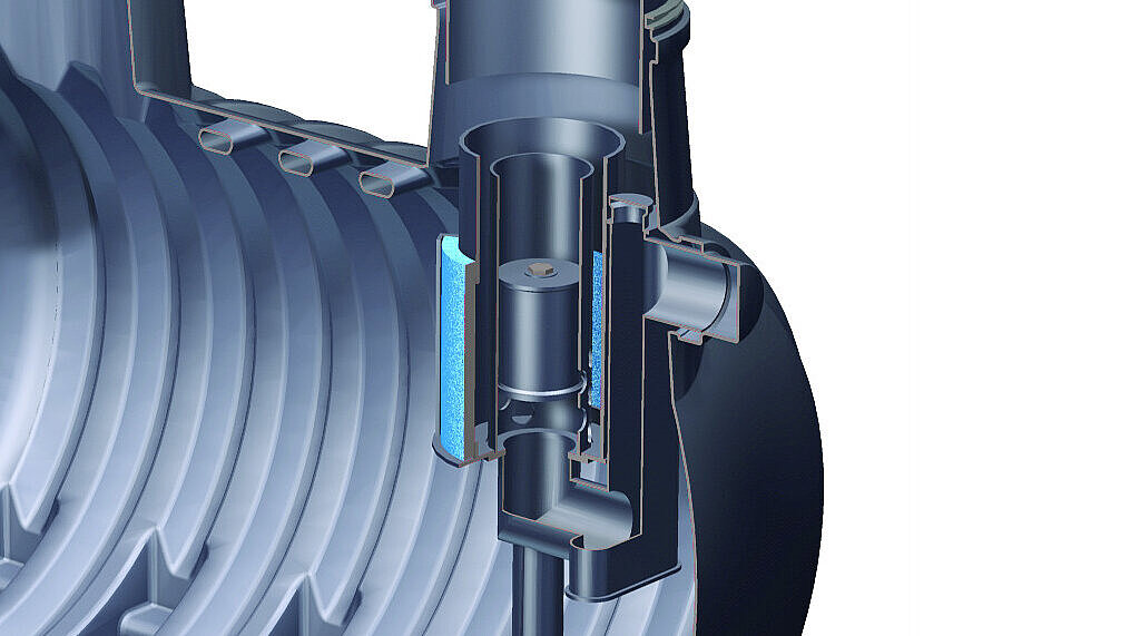
Oil/fuel separators and coalescence separators are fitted as standard with an automatic closure device. This device prevents light liquids from escaping into the sewer once the separator has reached its maximum oil storage capacity. In the KESSEL light liquid separator, this safety feature consists of a floater guide tube, which is filled with water during normal operation. The floater is calibrated so that it floats in water and sinks in light liquids (up to a density of 0.95 g/cm³). When the maximum oil storage capacity is reached, oil enters the floater guide tube through horizontal openings. The floater then sinks downwards and reliably seals the drain of the separator.
The automatic closure of a separator acts as an ‘emergency brake’. If it is triggered in the event of an accident/emergency, the separator must be taken out of service and serviced. Light liquid separators must therefore be serviced regularly and disposed of if necessary.